
Andrew's Corner by Andrew Kerr

Andrew Kerr
Read Andrew Kerr's "Consistency Is Made Before the Start" on Sailing World's Website
Andrew Kerr Interviews Don Erickson, organizer of 2008 Championships
Windward and Offset Mark Rounding - Part 1 (January 2008)
Andrew Kerr Interviews Jason Crowson (Sept 2007)
Andrew Interviews IV McNamara (aka All Roads Lead to Tulsa) (February 2007)
Winter Sailing (February 2007)
Lay Lines Revisited (October 2006)
Andrew reports 2006 EYC Memorial Day/Western Regional Championship
Andrew Interviews Blair Wallace (May 2006)
Team Practice Sessions - Making the Most of Your Time (Spring 2006)
Andrew Interviews Travis Wilson on his racing and the 2006 Class Championships
Andrew Interviews Doug Smith on Fleet 19 and the return of Fern Ridge Res.
Andrew Revisits Heavy Weather Racing from the 2005 Championships
Andrew Reports on the Class Championships (August 2005)
Andrew Interviews Kerry Poe (July 2005)
Pre Race Preparation (May 2005)
All Roads Lead to Cascade Locks (March 2005)
Spinnaker Pole Height for Good Downwind Speed (January 2005)
Changing Headsails (September 2004)
Heavy Air Downwind Sailing (February 2004)
Tactical and Boat Handling Priorities (April 2004)
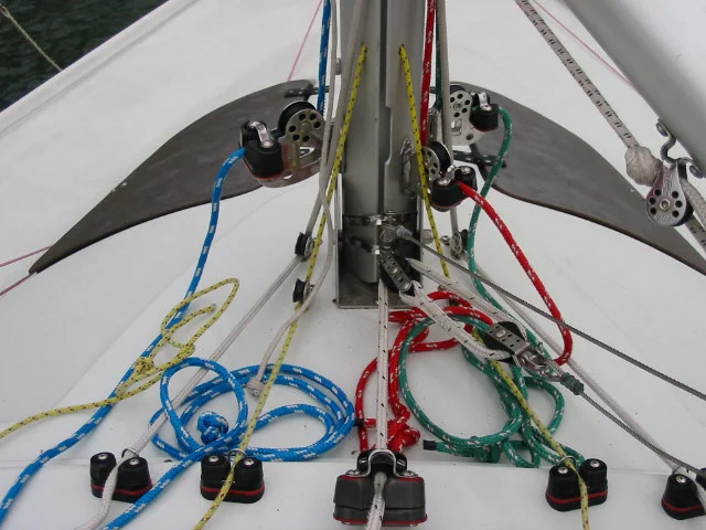
Rigging Set Up

Central Control Line for Aft Lowers, Internal Jib Halyard Fine Tune,

Swivel Cleat for vang, central control for aft lowers
Cascading backstay 24:1

External Jib Halyard Fine Tune
Light Line on Backstay
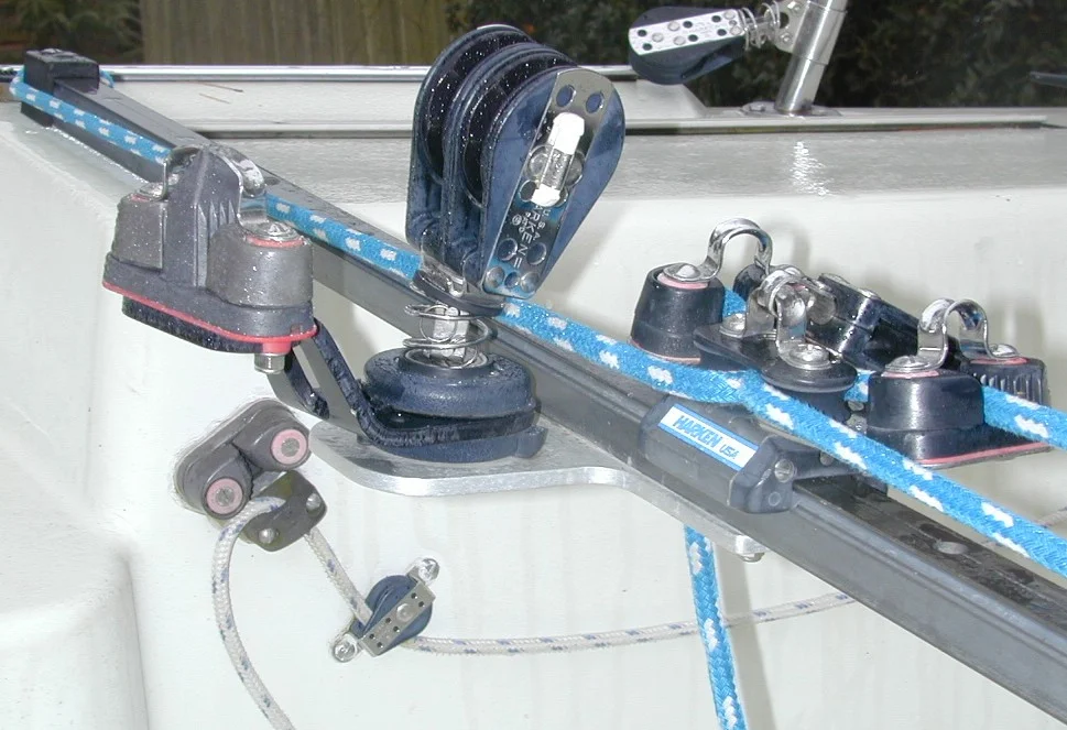
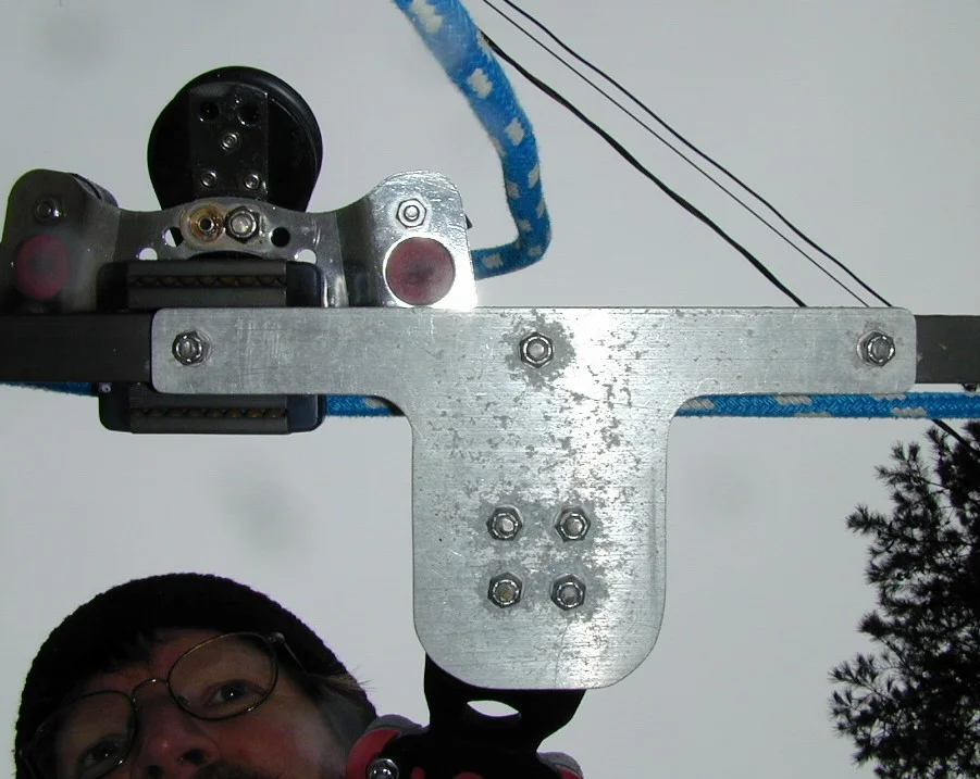
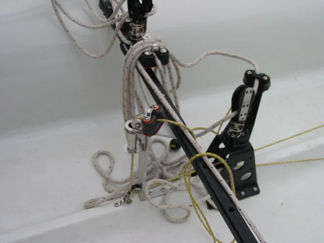
Mainsheet Barney Post Equivalent (Mounted on Traveller instead of Cockpit Floor) - Side View
Aluminum bracket bolted to Harken hi-beam traveler supports swivel mount for double ratchet main sheet block and double cam cleat for dual ratio mainsheet system from Layline. Double-ended backstay line and cleat on cockpit side beyond.
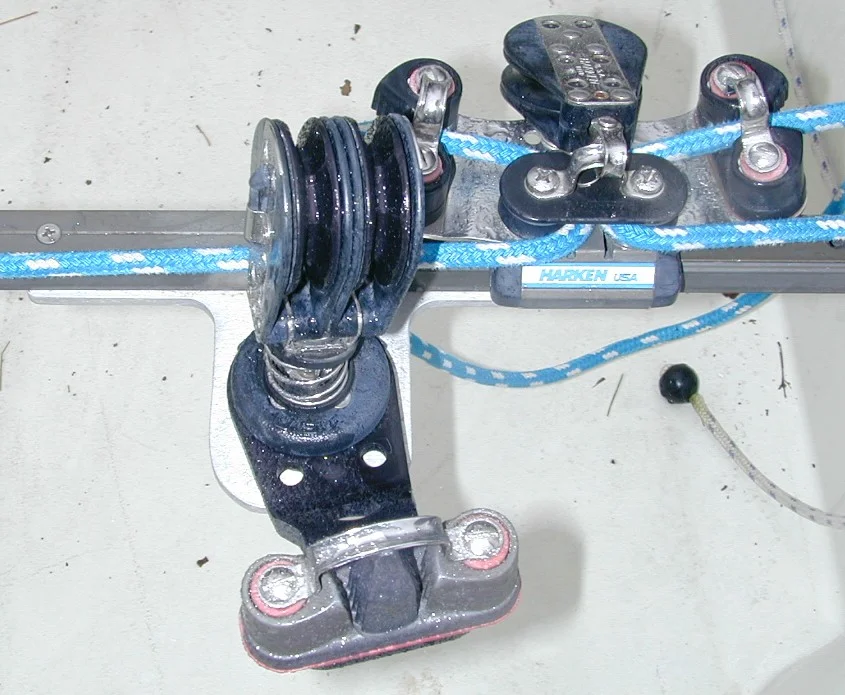
Top View
Mainsheet Bracket 2 = view from top. Bracket sized to provide clearance between track and swivel for car and control line to pass. Traveler car is high-load Harken with cleats mounted on car. Some people use a windward sheeting car.
View from Underneath the Traveller
Mainsheet Bracket 3 = view from bottom. Aluminum bracket (1/4" plate) bolted to traveler using SS bolts and nylon lock nuts. Ends of bolts are cut off to prevent damage.
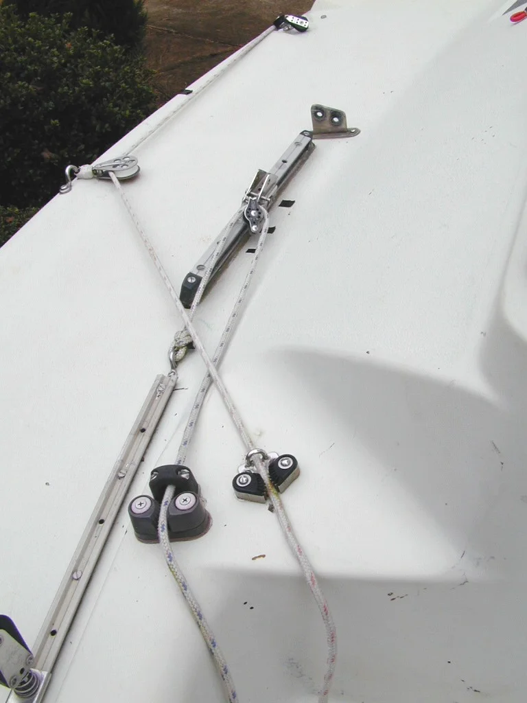
Aft Lowers Arrangement
Aft lowers 1 - Adjustable aft lower track made from old original main traveler track.
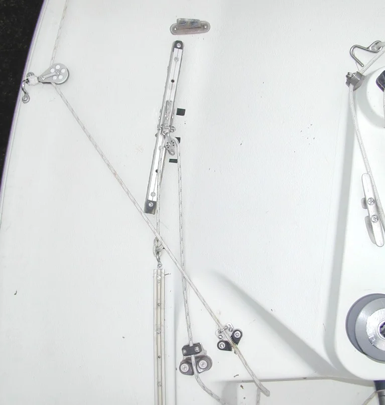
Aft Lowers Arrangement
Aft lowers 2 - 2:1 control line. Black marks on deck next to track indicate light, medium, and heavy settings.
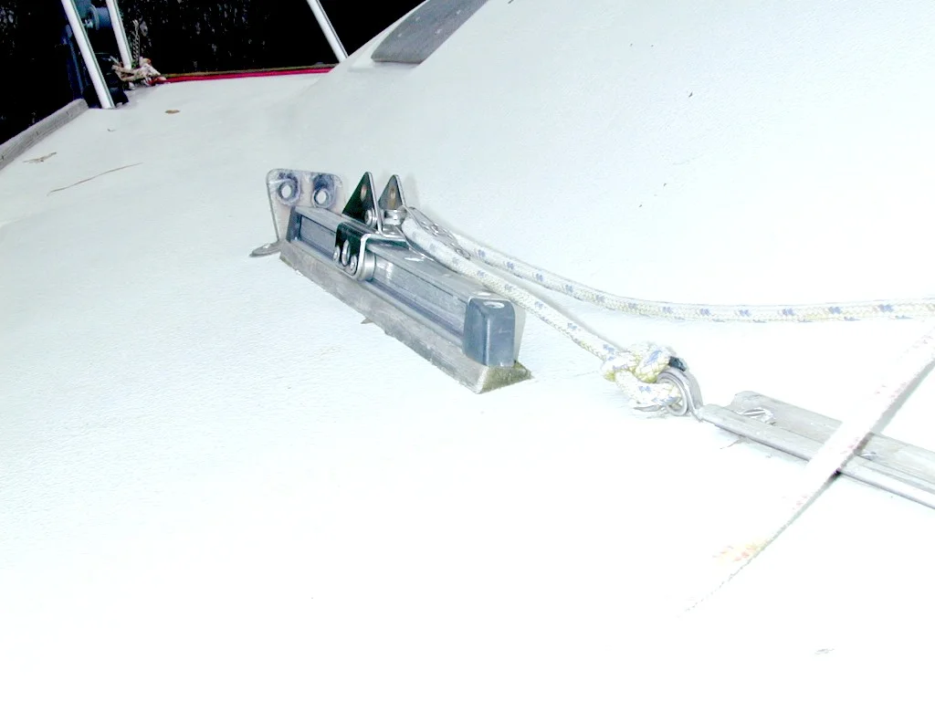
Aft lowers 3 - Track mounted on angled teak block to align track with shroud.
New Boat Console

New Boat Console - Side View
Backstay Controls - New Deck
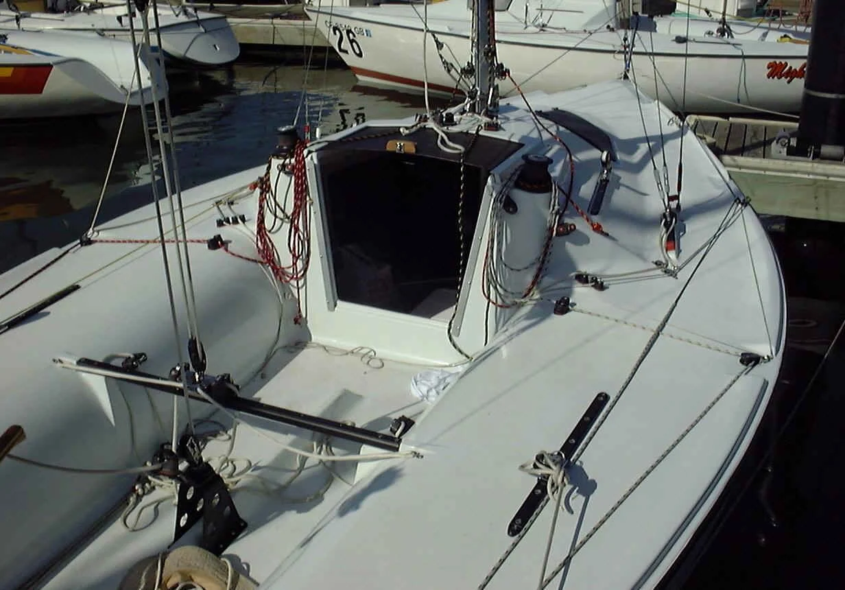
New Deck Layout (from year 2000)
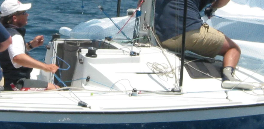
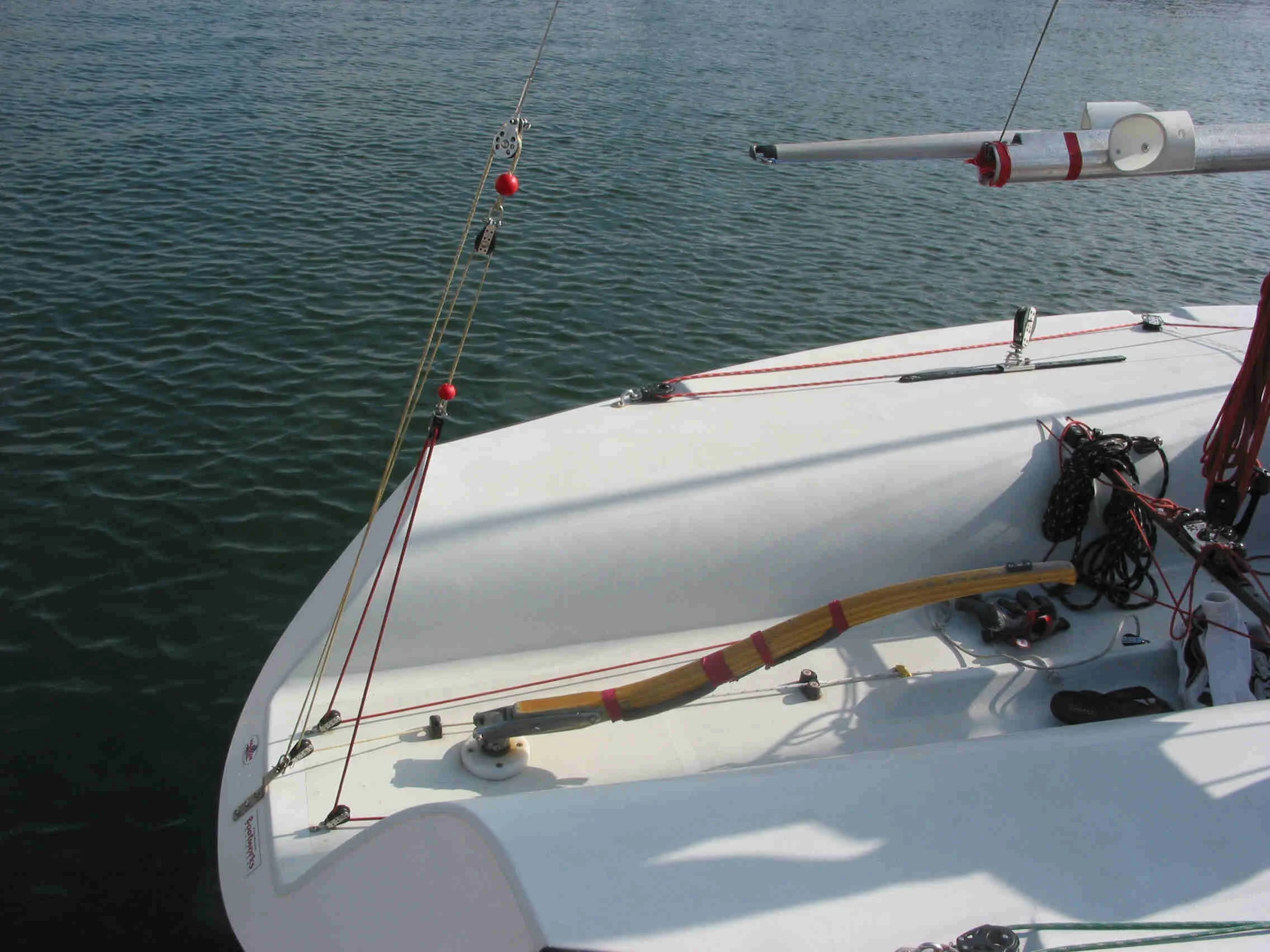
Disaster Area Rig Setup
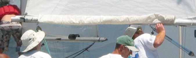
Sock on Boom used to hold Spinnaker Pole
Santana Tiller Fix
By Jay Aronow
Does your tiller feel sloppy? Have you tried to fix this problem by shimming the tiller fork with washers and tightening everything in sight? Well Jay Aronow thinks he has a quick and easy fix for this problem. I asked him to describe what he did to fix his tiller in a step-by-step description. So here it is, enjoy.
Okay..step by step to my best recollection:
You'll need a drill press, 22/64ths " bit, 3/8ths " bit, 3/8ths" coarse tap, 3 1/'2" stainless bolt with at least 1 1/4" of thread, 3/8ths stainless nut, 3/8ths" stainless Nylock nut, 2 stainless washers for the bolt and nuts, thin brass washers probably 4 but depending on how worn your fork is perhaps 5 or 6.
1. Remove the tiller and tiller fork from the rudder head and take the tiller off the fork.
2. Remove the rudder head from the rudder taking care to support the rudder from below so that it doesn't fall and get damaged.
3. With the head perfectly parallel to the work surface and using a drill press drill a 3/8ths inch hole in both sides of the rudder head. Do not drill through one side to the other but perform two seperate operations.
4. Now on one side of the tiller fork and with it perfectly parallel to the drill press bed drill a 3/8ths inch hole.
5. On the other side of the fork using the same care to keep the work parallel drill a 22/64ths inch hole.
6. On the side of the fork you just drilled tap a 3/8ths inch hole. I used a coarse thread bolt so of course I used a coarse thread tap but I don't think it matters if its coarse or fine. Be sure the hole matches the thread.
7. Smear a good water proof grease (I used Phil Wood bicycle grease because I had some) on all bearing surfaces and washers. Assemble the whole thing using the brass washers as bushings between the head and the fork and tighten the bolt very snuggly into the threaded side of the fork add the nut and again tighten very snuggly and now the Nylock snuggly. Now back off the nut against the Nylock to prevent any loosening. I cant stress enough the care that you must take to drill perfectly straight holes. Every thing must line up as perfectly as possible or you just end up with same problem you're try to fix. My observation is that the problem is not so much that the tiller fork doesn't match the rudder head but that the bolt is smaller than the holes. This causes the holes to get larger over the years with wear. The brass bushings are sacrificial and will need to be replace periodically and remember to lube the assembly every now and again. I have used this set up and although it's still fairly new I've done about 200 hundred tacks a close to 20 minutes of sculling and everything is just as tight as when first assembled as far as I can tell and it all moves together as one unit. It feel good to the hand and best of all its not sloppy all for less than three bucks.
Santana 20 Running Rigging Dimensions
Main Halyard 60' x 1/4"
Genoa Halyard 55' x 1/4"
Spinnaker Halyard 65' x 1/4"
Topping Lift 30' x 1/4"
Foreguy 13' x 1/4"
Backstay Adjuster 28' x 1/4"
Mainsheet 40' x 5/16"
Spinnaker Sheet 2 @ 50' x 5/16"
Spinnaker Tweekers 2 @ 10' x 3/16"
Genoa Sheet 1 @ 52' x 5/16"
NOTE: These are suggestions only. Your rigging lengths may vary based on the style of mast.
Santana 20 Rudder Bearing Repair
By Tucker Strasser & Ralph Taylor
So you've checked your tiller and it is OK, but your rudder still feels sloppy? Well your problem might be in the rudder bearing. Lucky for you Tucker Strasser has developed a way to repair worn out rudder bearings. He makes it sound so easy you will probably want to do it every time the relatives come over!
What better time of year than the Holidays, when the relatives are over, to repair your boat. If your rudder is loose from years of using it for propulsion before during, and after a race now there's an easy fix! YOU will need a wrench, a screwdriver, paste wax, graphite powder, and silicon spray. Buy the following:
105 West System Epoxy
205 Hardener
423 Graphite Power
(The epoxy mixed with the graphite will be self lubricating. For technical information or to order materials, call Gougeon Brothers at (617)684 7286, or Mike at Multihull Marine at (310)821-4647.) Also helpful, one small person, appropriate beverages, paper towels, Band Aids, and wax paper.
First chill the beverage then remove the rudder. Have someone hold the rudder so it doesn't fall and dent the driveway. Then get someone small, who doesn't complain too much, to crawl into the back of the boat with a screwdriver and remove the two hose clamps and then the rubber tubing. This will take some work, but it will eventually came off. Next wax the rudder post with a paste floor wax (such as Johnson's Paste Wax) and then spray it with silicon. Make a mix of epoxy and graphite and coat the inner bearing at the deck level and at the bottom. Tip: I used a stick to coat the inside as best as I could. Slide the rudder back in the hole and attach at the top. Note, it's a good idea to cover the rudder with wax paper as most of the epoxy will drip-out as you're attaching the rudder. Next, go back inside the boat and clean up the epoxy where the rudder tube attaches. Leave excess epoxy on the post since it will peel off later While the epoxy sets up, four to six hours, consume the beverages telling your spouse that you're too busy to help with whatever.
At the point when the epoxy has set Up (4-6 hours) rotate the rudder a few times to break the bond. It will be very stiff, but don't worry. Let it sit over night. The next day remove excess epoxy on the rudder post and remove the rudder. Reinstall the rudder hose, wax post again, and reinstall everything. If the relatives are still around you might want to get your crew and go sailing to make sure it all works. Now you will win all races! Happy Holidays!
Note: If the rudder is extremely loose check to see that it doesn't tilt to one side or the other. You want to keep it in alignment with the keel. If you have any quest ions, or heck, just want to talk about racing, contact rtswood@aol.com
Notes on Graphite/Epoxy Mix
By Ralph Taylor
So now you are asking "How much graphite to add to the mix?" To give a facetious answer, "Enough." The reason is that when you mix epoxy resin and hardener with other materials (such as graphite powder, micro-balloons, silica, cotton fiber, whatever) usually the consistency of the mixture is specified rather than the component amounts.
The consistencies are - from thinnest to thickest - syrup, ketchup, mayonnaise, and peanut butter. For small batches, I usually start adding the solid powder to the resin only, mixing as I go, until the mixture is a little stiffer than desired, then add hardener. If you judge right, the hardener will thin it down to the right consistency. After the first batch or two, you'll get the feel of how much powder to add at a time. I start with a volume of solid equal to the resin and keep adding and stirring until it looks right.
For this job you won't need very much. A few ounces of each should do it. I think peanut butter is the consistency you want, so the stuff will stay up there.
Be sure to wax the rudder shaft and turn it before the resin sets hard. Setting time will be determined by whether you use fast or slow hardener, by the temperature, and by how big the lump of resin is. (Bigger amounts set faster because the process generates its own heat.)
I would recommend using West System products, which you can order off their Web site, if you don't find them at your local chandler y or borrow from a buddy. West has everything you'll need, including the graphite powder. I recommend West because of the quality and their clear instructions. You don't want to do this job twice! Not because it's so hard the first time, but it would be really hard the second time.
Good sailing,
Ralph
Santana 20 Mast Measurements
By Jeff Kerr - S20 # 338, Fleet 15, Dallas
Since the Santana 20 measurement certificate does not provide every single detail of what should go where on the S20 mast, I thought this drawing from the Owner's Manual could be of help to anyone (like me) who has had to replace a mast.
A. Extrusion Length 26'8"
B. Bottom of Black Band to Deck 26'4"
C. Main Luff (Between Black Bands 24'6"
D. Centerline of Upper Shroud Bolt to Deck 24'5 1/2"
E. Spinnaker Halyard Exit 23'8"
F. Spreader Height 11'9"
G. Centerline of Lower Shroud Bolt to Deck 11'6"
H. Max Height of Spinnaker Track 65"
I. Top of Black Band to Deck 22"
Santana 20 Mast Step Compression
By Jeff Kerr - S20 #338, Fleet 15, Dallas
Amended for work by Greg Smith
The Problem
The classic Santana 20 has a wooden mast post inside the cabin that transfers the compression forces of the mast down to a marine plywood stringer that runs athwartship just in front of (or on top of) the forward keel bolts. This stringer is made of 2 layers of 3/4" plywood that are encased in fiberglass. The entire load of the mast is transferred into 2 square inches on the stringer. Along with the compression, a very large shear force is applied to the stringer.
There are 2 things that can cause the stringer to compress. The first is that first couple of hundred boats that were made had an air gap under the stringer down to the hull. When enough pressure was applied via the mast post, the stringer would flex. If the backstay were left on for a period of time, this flex could become permanent. The symptoms of this problem are typically poor performance in heavy air. The reason is that as more backstay is applied, the more the stringer flexes, and this effectively reduces rig tension. So the rig gets loose just when you want it to be tighter. This problem was realized by W.D. Schock and boats since then have been made with a fiberglass filler between the stringer and the hull.
The second cause of mast post compression is the way the stringer is cut to mount the keel on the boat. In order to get a socket on the forward keel bolts, part of the stringer is cut away with a hole saw. This is fine if you live in a dry climate or dry sail, but if the boat is left with water in the keel pan, the stringer will eventually soak up the water and get soft. So again when backstay pressure is applied to the mast, the compression is transferred through the mast post and the step compresses. If not treated this can cause some minor cosmetic damage, but severe structural damage would occur only after the problem is very visually obvious. Here is a photo of a mast step that has gone soft and suffered from the large mast post shear force.
The Solution
There are many half documented solutions in the Santana world. My first attempt to fix the compression problem started by cutting out the compressed area. As a temporary measure, I put in a piece of 4x4 lumber cut down to fit my cut-out area. This 4x4 was not attached to be stringer at all. The mast post rested on it and the 4x4 rested on the hull. I noticed very quickly that the the leading edge of the keel was starting to separate from the hull. When I removed the 4x4 and mast step (with the mast down), this separation went away. It could be that my hull is inordinately soft, but I didn't like the idea of transferring the mast post load to the hull.
A better solution was to keep the mast load as a closed system. Since the mast was connected to the shrouds and the shrouds connected to the bulkheads via the chain plates, I needed to get the mast post compression forces into the bulkheads. Since the stringer for the mast post is glassed into the bulkheads, the best solution seemed to be to spread the load of the mast post along the stringer. This would keep all the loads of the mast in one mechanical system. It would also keep my hull from deforming at the leading edge of the keel.
I had a 3/16" stainless steel plate made from this template at a cost of about $50. To install the plate, I sanded a bit where the outside edges of the plate would come in contact with the stringers, then filled the middle part with epoxy filler before using #12 wood screws to permanently attach the plate to the stringer. I also reinstalled the mast post before the epoxy could cure to prevent is from cracking once it became loaded. As with other methods, I had to use a hydraulic jack on the inside of the boat to get enough room to reinstall the mast post. I also cut about 1/4" off the post to allow for the width of the newly installed plate.
This solution has been in my boat for several years now. From looking at the repaired step it may be noticed that the plate has a slight bow from the load. This is probably because I weakened the step when I cut the big hole in it (although I cut the 4x4 down so it wouldn't touch the hull and put it in place with epoxy filler). In any case, my speed and heavy performance have increased. Most of the other boats in Fleet 15 have implemented this same fix and our boats were 2nd and 4th in the 1995 Nationals. In fact the boat from the above "soft" photos was 2nd!
Amendment
Greg Smith has come up with an alternate mast plate template. It can be downloaded here. It is a scanned image so it will look big in the browser. Save it to your local hard drive and open it with an application like MS Photo Editor or Adobe. Then you can print it out in a landscape format and force it to fit on one page.
Plate Template

Spinnaker Setup Notes
Following is a collection of excerpts/comments from the Bulletin Board. Descriptions below are the opinions of the person providing the comments.
Spinnaker Pole
I used 1 1/2" Forespar pole ends from West Marine at approx. $55 per end. Other ends are available (like RWO) through Defender, etc. For the pole I went to a Wire Rope supplier and ordered 1 1/2" Pike Pole tubing (which is anodized aluminum) I got 16' for about $30, and now have an extra pole in my garage. It was just as cheap to get 16' as it was to get 8'. If you have any questions let me know, It's much cheaper to make your own pole.
Greg Smith
Launching/Dousing a Spinnaker
Spinnaker is packed on the forward port hatch. You would normally have a spinnaker bag inside the boat and attached to this hatch. The popular configuration seems to be the use of continuous spinnaker sheets. Spinnaker sheets must go outside of the forestay and all shrouds.
The spinnaker halyard is the topmost exit on the mast. This halyard is led over the shrouds to the port side to a shackle attached to the port spinnaker ratchet block. This keeps the halyard away from the jib sheets. Just before you tack on the starboard layline to the windward mark, the halyard is released from the shackle so that the spinnaker can be hoisted. Instead of using a person to unshackle this, some have used rubber bands to hold the halyard. Others have also used velcro.
When you are on the starboard layline, it is time to set the pole. The pole arrangement varies. Some have it on the boom and others lay it on the deck. Attach the pole to the afterguy, and clip the other end to the pole car on the mast. The foredeck then needs to open the hatch and begin prefeeding the spinnaker. This is done by pulling on the afterguy back and forth until the end of the spinnaker is near the pole and over the forestay. Then position the pole back towards the desired position. Topping lift and pole car height is also adjusted to the proper position.
(By the way, the selection of type of pole arrangement - end for end, trolley system, etc. would be the subject of another topic. Also some poles have a bridle, some don't. Some use thick poles some use thinner poles. So let me know if you need help on this).
After reaching the windward mark and while bearing away, the foredeck can now hoist the spinnaker and the middle crew fine tunes the guy to the course and then begins to trim the sheet. The foredeck can now douse the genoa/jib, and place it under the bungee cord on the deck.
Twing lines (tweakers) are used instead of a foreguy on other boats. These lines are attached to the spinnaker sheets somewhere near the hatch area forward of the shrouds on the gunwale. These are trimmed during maneuvers (jibes) which keeps the spinnaker sheet/guy closer to the deck. This keeps the pole from rising and during maneuvers, chokes the spinnaker so it can be controlled. When on course, the sheet side tweaker is eased and the pole side is kept trimmed tight (almost to the deck).
On an S20, the spinnaker is always hoisted from the port hatch and the pole is stored on the starboard side. This makes a "jibe" set unlikely. To do the equivalent of a jibe set, you would have to either (a) hoist the spinnaker without a pole and attempt to balance the spinnaker in the center of the boat (a difficult manuever) or (b) jibe shortly after the bear away set.
To douse the spinnaker, hoist the genoa first. This will blanket the spinnaker so it can collapse. Then, the foredeck should release the spinnaker halyard (usually the foredeck will control the spinnaker halyard while forward) in a controlled way while grabbing the spinnaker from the port side. The foredeck will stuff the spinnaker directly into the hatch. If the spinnaker hoisted properly on the previous run, you will expect the spinnaker to come out properly again without any repacking.
In some cases, it is possible to douse the spinnaker on the starboard hatch (if this is necessary for the course) but this is usually only done if the spinnaker will no longer be used.
Roberto Cordero
Spinnaker Setup with Trolley System vs. End-for-End
My system is a lot like Robert described, it's a trolley system on a bungee around the mast. This does eliminate end-for-end jibes since the inboard end of the pole is attached to the trolley. so, you're locked into a "bayonet jibe" where the pole comes off the guy and the mast, is slid part way back along the main, then the main comes over allowing the pole to go out on the other side.
The extra lines attached to the sheet and guy are called "tweakers" or "twings" and they do provide some downward pull on the guy. (You want to have the twing on the sheet side off except in heavy air.) My spin sheets are run through blocks on the twings, but some use cunningham hooks so they can come off easily.
We've found that, in some conditions, the twings don't pull the pole down enough on a tight reach, so we have a foreguy that's rigged to the pole in heavy weather.
When the pole is stowed, we clip the forward jaw into a line at the gooseneck to keep it from bouncing around.
If you want to use end-for-end jibes, you can still stow the pole on the boom. You'll need something like a ring or cap at the aft end and something to clip it to in the front. You would rig the topping lift to the center of the pole or on a bridle. Rig the foreguy to the center; don't use a bridle here unless you want to strangle your crew. When the pole's stowed, clip the foreguy into the jaw to keep it out of the way and leave some slack in the topping lift so it doesn't destroy the shape of your main.
Where to hoist from: EVERYONE launches from the forward hatch - bags are slow. If you use a bag, you have to re-pack and re-rig before you can hoist again. with the hatch, pull the chute down into the hatch, close it and you can hoist again in a heartbeat. Don't untie any lines, or they'll be fouled when you re-tie them.
You can launch from and take down into either hatch; just remember the chute has to come out of the same hatch it went into.
Douses are usually done on the weather side of the boat, unless you want to make your foredeck miserable.
Ralph Taylor
Spinnaker Questions
1. What is on the front part of the pole to hold it up?
2. Do the topping lift and down tension lines remain attached?
3. Is it always better to launch out of one of the hatches or use a bag?
4. What is the best method of running the bungee lines to tuck the Jenny during a spinnaker session.
... On my boat, I attached the topping lift to one end of spinnaker pole end fitting and removed the foreguy(down tension sheet). To control the spinnaker pole from rising, I've attached a stand-up block to the port and starboard railing and about one foot in front the mast. A block is ran through each spinnaker sheet and is attached a sheet to the stand-up block and back to a camcleat by the cabin/cabinway. The spinnaker pole is a trolley system which hold one end close to the boom. The trolley line is a bungee cord attached to starboard clew of the boom the front the mast and then back to the port side clew. I stored one end of the spinnaker pole in a PVC cap near the tack of the boom. The shock tension keeps the polein the PVC cap until needed.
I launch my spinnaker from the port-side hatch since majority of my spinnaker setting is for a bear-away set. I've got two bungee cords running from the bow to the shrouds/aft lowers and then a small bungee cord with hook attached.
Robert Kontra
Santana 20 Rig Plan
The following table shows what rig measurements must be made on a Santana 20 to validate a measurement certificate and comply with the Class Rules:
Santana 20 Characteristics
LOA 20' 2 1/2" Displacement 1350 lbs.
LWL 16' Ballast - Fin 550 lbs.
Beam 8' Ballast - Wing 600 lbs.
Draft - Fin 48" Sail Area 186 sq. ft.
Draft - Wing 32"
FOR THE PURPOSE OF MAINTAINING FAIR SAILING, THE FOLLOWING MEASUREMENTS MUST BE MAINTAINED PLUS OR MINUS 3/8 INCHES ON THE RUDDER AND KEEL:
RUDDER
The thickness of the rudder section measured down from the top edge 3 inches is 2 1/16 inches.
The thickness of the rudder section measured down from the top edge 20 inches is 1 5/8 inches.
Intentional hollowing or changing of the cross section outside of a straight line top to bottom is not allowed.
The gap between the top of the rudder and the hull and between the front edge of the rudder and the rudder post may be filled with any material provided this material does not extend out from the profile or section of the rudder.
FIN KEEL
The thickness of the keel section measured down from the hull 3 inches is 4 inches.
The thickness of the keel section measured down from the hull 20 inches is 3 3/16 inches.
Intentional hollowing or changing of the section outside of a straight line top to bottom is not allowed.
WINGED KEEL
The thickness of the keel section measured down from the hull 3 inches is 3 inches.
The thickness of the keel section measured down from the hull 16 inches is 3 inches.
The thickness of the wings measured 3 inches from the outboard tip is 2 5/8 inches.
The thickness of the wings measured 5 1/2 inches from the outboard edge is 3 inches.
Intentional hollowing or changing of the section is not allowed.
NOTE:
A hollow of 1/8 inches is permitted on a straight line top to bottom of the keel and rudder. Under no conditions may the profile of the keel or rudder be extended.
The keel and rudder may be smoothed and made fair within the following provisions:
- It is allowed to add material to the hull, keel, and rudder to fill depressions.
Santana 20 Measurer's Rulings
- Spinnaker reaching struts, etc. The spinnaker guy is not to be considered a sheet for purposes of Article VI.6. , Design, Characteristics and Equipment of the Association's Bylaws. Accordingly, the spinnaker guy does not have to lead to the genoa track, but may lead through a reaching strut or to a block, bulkhead, or hook mounted other than the genoa track.
Aft lower shrouds. The aft lower shroud is optional and need not be fitted, may be fitted permanently, or fitted in a manner that is adjustable so long as the dimensions given in this rule are maintained. The aft lower shroud shall be attached to the mast at the same location as the intermediate lower shroud as shown on the measurement certificate.
The maximum that the rear lower shroud may go aft is 15 inches from the back side of the chainplates. This position is measured by projecting the aft lower shroud to intersect the deck.
All mounting points of the aft lower shroud must be located on a line 12 1/2 inches inboard from the outboard edge of the deck non-skid. The inboard measurement of the mounting line is determined by measuring at right angles from the deck non-skid to the mounting line at both the forward and aft ends.
- Internal hand holds, inspection holes, inspection ports, winch handle pockets and storage cuddies are permitted in vertical surfaces of the cockpit.
- Spinnaker launching and retrieving tubes are not legal.
- The hanks on the jib must be attached to the headstay when the jib is in use.
- Through-hull kelp removing devices are not legal.
- Internal tangs in the mast are not within the one-design concept of the Santana 20 Class Rules and are not legal.
- Inspection holes in the V-berths are legal, but covers must be kept in place while racing.
- Bainbridge 404 Dynac cloth is not acceptable for the spinnaker because its base fabric is 1/2 oz. material.
- Roller furling gear is not legal.
- The bearing point of the spinnaker halyard when held taut at right angles to the mast may not be higher than 23 feet 8 inches from the bottom of the mast extrusion. Any exit arrangement shall not extend out from the mast farther than necessary to clear the forestay.
- Reefing the working jib is not legal.
- "Membership" in Article IX.7 of the Articles of Association is deemed to mean membership in good standing with dues current.
- When using a cunningham on the jib or genoa, the tack of the sail must be attached to the stemhead fitting of the boat and the cunningham must have a separate eye in the sail.
- The intent of Article IV.2 of the Bylaws is not to prohibit the measurement of specific items at the Class Championship Regatta.
- A mainsheet system that does not employ the traveller and changes the positioning points on the boom for the mainsheet attachment is illegal.
- The intent of the spreader design is that the spreaders should be in a straight line (perpendicular to the centerline of the hull). Therefore, it is illegal to employ swept back spreaders.
- Any protrusion in front of the rudder, in this case intended to keep kelp from getting caught on the rudder post is illegal because it is an alteration of the hull shape.
- Tubes used to guide the backstay lines forward to the middle of the cockpit are legal.
- It is legal to use a line to position the genoa cars; however, in keeping with the spirit of the rules, the system shall be simple and shall not use magic boxes, winches, or hydraulics.
- In Article VII.5 of the Bylaws, "sailing season" is interpreted to mean the first calendar year in which the boat is owned.
- It is legal to use a shackle in place of the bow fitting hooks so long as the shackle adds no additional function or advantage. Swivel shackles would be illegal.
- Any type of stiffening or strutting for the purpose of stiffening the deck or hull is illegal.
23.AThe lone exception to this ruling is that a short bracing line may be run from the underside of the aft end of the checkstay track down and forward to the lower main bulkhead. This will prevent the deck from lifting and developing a weak spot when the aft lowers are brought into tension. However, it is imperative that the lower bulkhead attachment point be longitudinally in-line with the checkstay track attachment point, be well-backed, and be low enough that the mounting bolts go through both the main bulkhead and through the aft vertical wall of the vee-berth box structure. This will ensure that the minimal load is spread evenly through as much of the structure as possible. See attachment
- It is interpreted that Article IX.7 of the Bylaws means that the helmsman must satisfy the regatta requirements and that he must have satisfied them as helmsman.
- REVISED 2007: A backstay that has any part beneath the deck does not meet the requirements of Bylaw Article VI.3. "Classic" decked Santana 20's may attach their backstay at the base of the transom and may run their backstay adjustment lines through the transom and into the cockpit through the cockpit's rearmost vertical wall only, so long as the material used in the transom-cockpit passage is rigid, well-sealed, and does not compromise the strength or watertight integrity of the hull. Click here to read more.
- The Santana 20 Class is not an international class recognized by the I.Y.R.U. Therefore, I.Y.R.U. Rule 25.1 does not apply. Under Rule 25.2, the Santana 20 Class authority requires only racing numbers, no national letters. In the case of yachts from countries which do not use the sequential numbers from the Santana 20 Class, they may use their own numbering system if used in conjunction with their national letters.
- The use of Mylar cloth for spinnakers is illegal.
- Main sails without extended battens purchased prior to March 1, 1989 will be measured under Article VII of the 1988 Year Book. Any sail with extended battens and all sails purchased after March 1, 1989 will be measured under Article VII of the Bylaws.
- The transom radius shall be 5/16". No sharpening of the radius shall be permitted.
- 2/15/2005: The use of carbon fiber spinnaker poles is illegal. Click here to read more.
- 4/13/2005: Repairs to the boat are legal if they meet the following conditions:
1) the repair does not impart an obvious improvement, relative to a factory original Santana 20, in the overall performance of the boat.
2) the materials and reconstruction methods used in making the repair shall be comparable to those used in the original boat (aka "faithful reproduction") except
(a) when a boat damaged during competition would be prevented from returning to the same competition due to the lack of time, lack of appropriate materials, or lack of expertise to carry out a "faithful reproduction."
(b) when alternative materials and reconstruction methods are commonly available and offer a lower total repair cost as compared to a "faithful reproduction."
[CM Papadopoulos. This ruling was approved by the Governing Board on 4/13/2005.] - A batten may be attached to the masthead crane at one end and the back stay at the other to help clear the leach of the main.
- Oct. 2010. Non-wire/rod backstays and checkstays are Class legal. However, the upper/lower shrouds and the forestay will remain of wire/rod construction.
From: Chief Measurer
Date: February 15, 2005
Subj: Carbon Fiber Spinnaker Poles
Q: Does the Santana 20 class currently allow carbon fiber spinnaker poles?
A: No. There appear to be no Santana 20 Class rules that allow poles that differ from the standard equipment provided by the S20 builder (i.e. aluminum) so by default a carbon spinnaker pole is not allowed.
There are three class rules that apply (which you can find at www.s20.org under the Association and Measurement sections) to changes in equipment when no prior rulings exist to guide us. They are:
1) Articles of Incorporation Article III.2 - Relating to keeping costs of
upkeep within modest limits
2) Bylaw Article VI.2 - Changes are illegal unless specifically allowed
3) Bylaw Article VI.5 - Substitute hardware allowed if there are no
functionality changes
The first two rules set our overall strategy and are the basis of not allowing the use of carbon in making S20 spinnaker poles. The third rule is the only rule that theoretically could allow a carbon pole but this rule is commonly interpreted to apply only to the fittings permanently attached to the boat that, over time, become obsolete and worn out and must be replaced with "not factory standard" components. I interpret this rule as NOT being appliable to the spinnaker pole because the pole isn't a permanent part of the boat and there is no difficulty in finding brand new aluminum poles that are exactly or nearly exactly the same as those provided by the builder.
In summary, two rules against the proposal and one rule that is marginally in favor of the proposed change leads to my no decision.
+John Papadopoulos
S20 Class Measurer
Weighing the Santana 20 Project
On June 4, 2010 Santana 20 Class Association President Derek Martin publically announced a project to weigh Santana 20 boats using a scale purchased by the Association. The original announcement is available here... Original Project Announcement
On July 27, 2010 the first report on weighing was publically published. The report is available here... Boat Weighing Project Update
Weighing the Santana 20
June 4, 2010
By Santana 20 Class Association President Derek Martin
A long standing issue within our one design class has been how to best measure the weight of our boats. Our measuring rules have long called for the use of float tests (with float lines marked on the boat) but we know that this method can be difficult and inaccurate. The alternative is to use an accurate weigh scale however there are complications with that too – expense, access to hoists, setting a weight specification, etc.
The time is right to make a change but it must be done with great caution, patience, and support and participation of the membership.
To start the process, the Governing Board of the Santana 20 Class Association recently purchased an excellent quality 2000 lb digital weigh scale and has sent it to several fleets to collect data on the weights of our boats. After conferring with US Sailing and other Classes, the boats will be weighed with only hatches, floorboards, and spinnaker poles. As of this memorandum, 22 boats in Eugene and 10 in San Diego have been weighed with the new scale. The Oklahoma fleets will get the scale next, and this should be complete in the next two weeks.
Building a database is the first step in determining the minimum weight for a Santana 20 boat. Note that the boat is marketed as weighing 1350 lbs. The next step would be to develop weighing procedures (what gets weighed, etc.). The final step is to amend the Bylaws of our Association to make the weight and procedures cast in stone. This last step, of course, only happens with the consent of the membership – via a vote.
It should be noted that the weight of a boat does not seem to be a good indicator of how well the boat will perform; known heavy boats have performed very well while known light boats have performed worse. More weight data will help us understand if there is a correlation between the weights of our boats and how well they perform.
What follows are several questions (and our answers) that we imagine you might ask.
Why are we doing this? Has it been a problem in the past?
There are two main reasons.
First, using float lines is an inherently inaccurate, time-consuming, and manpower-intensive task. It requires the water to be absolutely glass-smooth, the boat to be level and motionless, and if a boat is underweight – multiple trips to the weight locker as weight is incrementally added. Anyone who has ever gone through this will tell you what an absolute pain in the rear it is.
Though not a reason to change, it appears that our class is increasingly in the minority by continuing to use float tests – most are now using scales to weight their boats.
Second, weighing boats with a digital scale is easy, fast, and accurate. Pull the boat up to hoist, hook on, raise the boat just enough to get her off the trailer, take the reading, set her back down, and move on to the next boat. Since the boats will be weighed empty (with only hatch covers, spin poles and standing/running rigging on the boat), this can be done while the sails are being measured separately, thus improving the rate at which boats can be measured at an event. With the current procedures, the boats are floated with all of the above onboard, plus sails, life jackets, floatation devices, etc.
In the past, none of this has been a problem, mostly because float testing was not conducted. Though float lines were marked on the boat, they only served the purpose of being able to conduct a proper float test should the need arise (e.g. as a result of a protest). The last Class Measurer to actually go through the procedure as it is written was John Papadopoulos back in 2003. You can ask him (or anybody who went through that measuring process) how much fun that was. So we currently have a set of procedures that nobody really wants to use. That does not bode well for the long-term health of a one design class.
What will be the plan for determining the minimum weight of the boat?
There are two obvious choices: leave the official weight at 1350 pounds, or specify a heavier weight. Of the 32 boats weighed so far (with only hatches, sheets, and a spin pole aboard), nobody came in under weight. So the first choice is easy, the second one more complicated.
First off, let me just say that I understand that anytime you start playing with the minimum weight of a boat, many boat owners will experience a certain level of anxiety. After spending thousands of dollars on a boat, keeping it in fine racing shape and legal, a boat owner will be rightly upset to find out that rules have changed in a way that may impact him/her.
If we choose to move to a higher weight, there will be several competing factors at play, including: preserving the weight of a new-build boat, ensuring the value of “heavier” boats, not penalizing those owners that have worked hard to keep their boats light.
After talking with one design experts at US Sailing Association, other class presidents, measurers, and Tom Schock (who wholeheartedly supports this effort), what we need to do is come up with is a weight that our class feels comfortable with.
Every one design class is different and has its own personality as to what level of sophistication they want to go with something like this. This requires discussion, and the more brains we have contributing to this effort, the better.
We will be publishing all the data after the weighing efforts are complete, so that everybody will have a look at it, and you can offer your own conclusions and recommendations. As it stands right now, we hope to have somewhere around 40 boats weighed, and with a current registry of around 90 boats, this is a very good sampling.
Only boats that have been dry-sailed (meaning they have not been sitting in the water when not in use) have been weighed for our purposes. Obviously we can’t weigh every boat in every fleet, so we have been concentrating on the bigger fleets. Each fleet that has been weighed already knows what their group results have been.
Once we are complete with the Oklahoma boats, we will publish all of the data and let the discussion begin, using the forum on wwws20.org as our primary venue. Hopefully responsible and mature discussion will ensue.
Does the Governing Board have a time-line for bringing this to conclusion?
Yes and no. The general plan is to get a good database built up first, then start the discussion among the members. As the discussion continues, there will be probably be two or three competing plans that will emerge.
At some point, the Governing Board will determine that the discussion phase has run it’s course and will come up with it feels is the best course of action, based on the wishes of the membership. Then, the Board will present a draft wording of the changes to the Bylaws, and will then let the Membership comment and suggest changes. The Board will then make changes as needed, and then present the final version to the Membership for a vote (probably electronically). We really want to take our time on this and get it right, and there is absolutely no need to rush this process. The rules and procedures we have in place now will continue to work just fine, as they have for the last 33 years. I think an acceptable conclusion to this process would be to have it complete before the end of the calendar year (2010) and in place for the 2011 Nationals at Oklahoma City, but the Board is not wedded to it.
Will this have any impact on the measuring-in process at the 2010 Nationals? Will my Measuring Certificate still be valid?
Your current M/C will still be valid, and the existing procedures will be utilized at Huntington Lake. We are hoping to have the Membership engaged and educated in the process so that we can have a good discussion at the Annual Meeting.
Are there any dangers in doing this?
Yes, there are. Change is scary and uncomfortable. The old adage of “if it ain’t broke don’t fix it” may very well apply. If the official weight changes to something more than 1350 pounds, some owners will have to add some weight. If the weight isn’t set higher, some of the owners of heavier boat may feel at a disadvantage and discouraged.
As our boats age, it will be increasingly common to rehabilitate them and that may provide an irresistible opportunity for some owners to seek out ways of saving weight that might not comply with the spirit or the wording of our class rules.
We have been a fairly laid back class and we do not get overly hung up on minutiae, so again let me restate the mission of our efforts: (1) develop scale-based weighing procedures, and (2) develop a weight that the Class is comfortable with.
On the opposing side of the question, a well thought out minimum weight can be a great asset to a one design class. This will be the first time in the 34-year history of our Class that the Membership has tackled this issue. It will be well worth it in the long run and I hope you will join us in the spirit of helping ensure a vibrant future for our great one design class.
Hope you all are enjoying the water, warm weather, and our great boat!
Derek Martin
President, S20 Class Association
Archives of Members Responding to Members
Subject Headings: Boat Handling, Repair, Equipment, Rigging, Launching, Trailer
Boat Handling
- Steps to maximize boat speed -
If you were to have a fast, dry, old deck boat (#600+), that is raced in a competitive fleet, what would you do to make it better on a budget (aside from getting a new deck). All running rigging is replaced on a regular basis, lifelines removed, Mast is in good shape (sheevs etc all work well), have aft lowers, new sails regularly, main track moved forward, jib tracks set up in right place, backstay is set up optimally, pole on boom, twings in correct place, no extra weight below, basically have all the go fast goodies set up (aside from external purchase on jip halyard, fraculator line and stuff is not set up to trim from rail).
Reply:
A few things that you might already have.
#1 - clean bottom
#2 - get that jib halyard fine tune installed for proper head sail shape.
Other minor things:
Nylon ramps under check stay tracks to give maximum forward lean mast when flying spinnaker?
Rough tune and fine tune for back-stay?
Windward sheeting traveler (not cheap unless you can pick up a used one.)
Minimum running rig line sizes - no more than 1/4" except for main sheet?
Cover stripped on halyards except where handled and cleated?
If you sail in much light air:
1. Cover stripped from outboard end of spin sheets for less weight dragging on the clew.
2. Same for outboard end of tweakers; use small rings or similar in lieu of blocks for reduced weight on spin-sheet
3. Back-stay flicker batten at top of mast with composite back-stay (1/8" Amsteel Blue works well) to clear main on tacks.
- Dip Spinnaker Pole or End Over End -
Kind of curious as to what most do when jibing the spinnaker. End over end seems to work, and it looks like with at least my spinnaker pole that dipping also works. Anyway I'm curious what most do.
Reply 1:
By "Dip", do you mean: drop the old guy out of the outer end, swing the pole thru the foretriangle without removing it from the mast ring, and then somehow getting the new guy into the outer end ? If so, I've never seen it done on a Santana 20.
The two methods that I've seen are end-for-end and the trolley/launcher, with many more end-for-end boats around.
We use end-for-end and do it from the companionway so that no-one goes onto the foredeck. It allows us to jibe the pole before jibing the main.
With the trolley/launcher method, there's a piece of shock cord that goes from the end of the boom around the mast and back to the end of the boom on the other side. A block rides on this shock cord and is attached to one end of the pole. Jibing is accomplished by detaching the pole from the old guy and stowing it on the boom, jibing the boom and then attaching the new guy on the other side.
The pole is there to provide stability by keeping a second corner of the chute under control. I'd rather let it loose while we're going straight than when we're jibing the main upwind of it.
- Backwinding Main -
When I sheet in the Genny to the trim guide specification (1-3 inches from the shouds, 2-3 inches from the spreader), I seem to be getting a lot of backwind on the mainsail. No matter how much I sheet it in (the mainsail), it still backwinds on the first 1/5th of the sail at a minimum. It almost seems like the genny is causing the main to backwind. This obviously slows me down going upwind.
Reply 1:
It sounds to me that jib lead is to far forward with to much headstay sag. Start with that.
Reply 2:
Remember, front of the jib, the back of the main. these are the areas which HAVE to "see" the wind. My Husband is our trimmer. He likes a main that is a bit back winded in the front. As long as the tell tales are flying and the back of the main is "seeing" the wind, we are fast.
you may be ok.
Reply 3:
Too much forestay sag and the lead too far forward could well be the problem - the mainsail could also be too full - try more outhaul and Backstay (if overpowered) to flatten the sail. Be sure not too overtrim the genoa , which is easily done and can cause the boat to go slow and low.
Repair
- What should I look for as potential problems with an older boat -
I have an opportunity to purchase hull #432. From the pix (I have not inspected in person), it appears to be in rough shape. Owner sez it's not been hauled or sailed in +3yrs. Without a haulout, what should I look for as potential problem areas? All the standing and running riggings appears intact, although I assume much of that will have to be replaced due to exposure.
Reply:
Delamination of the deck, separation of the hull deck joint, Mast compression at the step down below near the keel are all common problems but very fixable. Broken hatches seem to be the most common. Tiller goose necks seize up too. I have made my own parts, but possible Schock can still get you what you might need.
- Forward Hatch Latch -
The forward hatch latches on hull #79 are a troublesome. Looking for what you've tried that has worked and what has failed.
Reply:
Most of the boats that are raced take the hardware off the hatch and replace it with a soft attached bungie connected to both hatches. This reduces the number of things to snag the spinnaker on and makes it easy for the foredeck to pull the hatch open. Make sure the bungie is stiff enough to hold the hatch down in a blow.
- Gap Between Keel & Hull -
While inspecting my purchase the other day I discovered that the top of the keel is pulled away slightly from the hull. It is just the at the leading edge, the gap begins right at the front at about 3/16" and then reduces to nothing over about 6". Is this the start of some failure that I need to be getting taken care of.
Reply:
Most likely the stringers in the boat are soft, but alot of the boats around here have a slight gap at the front of the keel. Alot of people just seal it up with your choice of product and go on. My hull is starting to do it but I plan to pull the keel this coming winter and put in new stringers that the keel bolts run through and I think that should solve most of the problem.
Reply 2:
I plan on a nice line of 5200 filled in and smoothed over.
Reply 3:
I replaced my stringers and mast base with structural fiberglass sheet stock from McMaster Carr. great stuff, easy to work with, rot proof, and once I retightened the bolts, any crack was null.
- Mast Post Compression -
would like to address the mast compression issue I have which is not horrible as of yet. Do I remove the fiberglass casing and replace the stringer underneath? Since that is what gets soft and sinks, I thought that might make sense to do before I add a plate on top.
If I find the forward stringer under the mast is soft, then should I also check. And replace the boards under the pan that sits above the keel and the keel bolts through?
Reply:
Ok, so it took one day to cut out the old bulkheads and floor stringer under the mast post and remove the other two keel bolts and the boards beneath them. All were soaking wet. I know its a boat, but to enclose wood in fiberglass that will inevitably get waterlogged seems like wasted effort.
The bulkheds I replaced with the same 1/2 inch marine plywood.But. To improve on the materials used under the mastpost and the blocks for the keel bolts was my goal. I decided on G10 material from McMaster Carr. The G10 is available in sizes that match the thicknesses I needed and, although $50 more expensive than wood, was relativley easy to work with, came very quickly in the mail, and has near zero compression, and near zero moisture retention.
FRP material from the same company does not come in the thicknesses I needed, but it is cheaper.
It took another day to cut the board and glass them in. Really, this is a one-day job if you have all the material on site, but it takes a day to get all the dust out of your respirator and clean the boat.
I took pics of the process and will happily send to anyone who needs them.
FYI, when I put the mast up last week, I had to re-tune the rig to compensate for the 1/2 rise in the mast.
- Mastbutt Mushrooming -
The base of my mast is showing a slight bit of mushrooming. I see that it is suggested that a piece of wood is placed inside the mast. How does this work exactly?
Reply 1:
I did this repair by shaping a 1 inch thick piece of teak into the shape of the mast extrusion. Inserted it with a small amount of wood showing past the aluminum. Drilled and threaded 4 short stainless wood screws. Re-shaped the mushroomed aluminum to make it flush with the wood. Finally, sanded the excess wood flush with the base of the mast. Looks and functions great as it spreads the load evenly.
Reply 2:
Once you have some mushrooming, it's hard to get a well fitting plug into the end of the mast. When I built the new mast, I cast a 2-1/2 - 3 inch thick plug out of West and high density filler in a waxed piece of broken mast of the same section. I drilled a 1/2 inch hole down the center for a drain and line-drilled 4 hefty SS flat-head screws around the plug assembled flush in the end of the mast. The foot of the mast needs to be square laterally (so that both sides of the butt share the load equally when the mast is laterally straight) and rounded somewhat longitudinally (so that it's not standing on a corner when you rake it back or fraculate it forward). I also found that the mast butt bottomed on the bend radii in the bottom of my partner fitting without sitting down flush. I flattened parts of those radii with angle grinder & sanding block.
Reply 3:
I took my new extrusion – after I had rounded the forward and aft edges of the butt – to a macine shop. I had them weld in a 2-3 inch high (don’t remember now) contoured inner aluminum sleeve. $50 -$100, but I never have to think about it again.
- Fiberglass Irritation -
I have had a sensation in my elbow after resting it on the deck that reminds me of the "prickly" effect I'd get as a young man when I helped friends/family install fiberglass installation in their homes. I is also not just me. My crew also gets this on her knees when rigging the jib, or when leaning out while working the tiller.
So, has anybody else experienced something like this, and if so what did you do? Is deterioration of the fiberglass in the hull something that I should be concerned about now and moving forward. Any thoughts would be much appreciated.
Reply 1:
The prickly feeling is very normal. It is fiberglass shards. Considering how old your boat is this is normal. Scrub the deck really good with a stiff brush, but try to buff out the smooth areas with a good fiberglass polish to try and seal in the gelcoat. I use Flitz metal polish. It really works good on fiberglass and aluminum.
Reply 2:
The likeliest source of glass fibers is any of the three hatch covers. They were built without gelcoat in order to remain translucent. If there are spots on your deck where the gelcoat has worn thru, they could also produce fibers. Gelcoat is the colored surface of the layup and contains no fibers. I have never heard of fibers migrating thru intact gelcoat from the layers below.
I coated my hatch covers with catalyzed polyester resin and was not very satisfied with the life of the coating. My next attempt will probably be some sort of two-part urethane coating concocted for full sun. With non-skid grit in the case of the forward hatches...
Reply 3:
Mix up a new batch of fiberglass resin and brush or roll it on. It will last a few years and need another coat. Also with the loose fibers it gives it a non-slip surface.
- Rubber Insert on Rub Rail -
I have no gunwale guard trim insert on my boat. I've contacted WD Schock and apparently the supplier they were using is no longer around. Anyone have any insight on what I need to buy and where to get it?
Reply 1:
Are you talking about the rubber bit that slides into the metal bit?
If so go to your local powerboat supply shop. Probably one that supplies older bass boats if possible. I know the my rub rail is identical to the ones on an old ranger bass boat my dad has. Surely someone still makes some that will fit.
- Boat Painting -
If you wanted to paint your hull and you had access to appropriate facilities and a skilled operator, would it be better to spray or roll the paint?
Reply 1:
Spray
- Water Around Keel Bolts -
Just back of the mast post, there is a cavity that has 2 keel bolts. it then leaks out through a .5 inch crack in the low area between the other keel bolts. The water level in the 2 bolt area gradually goes down as it leaks out of the crack.
Is this a serious problem that needs to be looked at?
The issue is should water be getting into that area below the fiberglass ( or whatever the base is made of) between the other keel bolts.
Reply 1:
Check the tanks. H20 could be going there and if that is the case alittle epoxy or glass could do the trick. If they are dry, then, well....... Check the keel hull joint etc....
Repy 2:
Is the boat left in the water or is it trailered? Is the water getting in before or after a sail? I wouldn't worry to much if the water goes back and forth between the keel bolts, but it does sound like you might have a mast compression issue that is cracking the fiberglass on top of the forward keel bolts. There are several fixes listed on this website. Water can get in even between the deck and hull and of course work its way down to those keel bolts as they are the lowest section of the boat. If you look carefully that fiberglass piece is an inner liner that gives the the boat stiffness. It is not meant to be water tight.
- Rudder Bearing Replacement -
I didn't know what to call it, but I am assuming all of you know what I am talking about. It is the 1/4 - 1/2 in spacer made of darelon, or something like that, between the rudder head and the deck. It is an old deck boat. The one in there is original, slippery, very fragile (crumbles like glass when scraped), worn down and cracking in 3 places. I figure I can just replace it with PVC or something similar and Mclube the crud out of it before every race, but I wanted to know if anyone had any other solutions.
Reply 1:
I made mine out of high-density polyethlene. It is readily available, cheap, and easy to cut. You can make several for minimal cost. Since it bears on the plastic nut at the top of the rudder post at deck level and the head of the tiller sits on that, it doesn't require anything fancy. Using a large washer or stainess steel disk between the tiller head and the plastic bearing disk would help spread the load more evenly and reduce wear as well as keep the sunlight off. I would not grease it otherwise grit will accumulate and increase wear.
Of course if you can find a sheet of teflon that would be great. You can also use torlon - the stuff used in ball bearing cars - it is much harder but also harder to shape and more $.
Reply 2:
I'm not sure why you couldn't make it out of UMHW. (Ultra High Molecular Weight Polyethylene) I use all the time. It's very easy to work with. Drills easy, needs to be cut with a table or chop saw. You can use a tap on it also. It's used in manufacturing and is almost indestructible with metal. I buy remnants of it by the pound. Cheap!
- Cockpit Floor Support Repair -
The fiberglass covering to the floor support on my older boat split allowing water to get to the wood. The support piece (2x8) is quite waterlogged, so I am tempted to replace it. Has anyone worked on this portion of the boat?
Should I replace the piece with fresh wood? or will plastic composite be "OK" with class rules? I do not think I will be able to allow it to get completely dry before I make the repair. My guess is that if I cover the wood when it is damp it will just split again when the warm weather comes.
Reply:
We had a similar problem a couple of years ago. We replaced the wood with a new piece and glassed over it. Pretty easy actually except for the confines of the space. Personally, putting anything besides wood in there is not really worth the weight savings.
- Rudder Repair – Depression -
I noticed a slight depression in my rudder, about 4" in diameter, about a year ago and thought it just wasn't faired that well. The depression has been getting worse. It was recommended I drill a hole and fill the depression with epoxy to stabilize it. I drilled a 7/32" hole to find out what the core material is and it is a foam core. Does anyone know the cause of this? The foam appears to be dry, so I don't think its moisture related.
I'm not quite sure I follow the concept of what he is recommending, since there is no gap between the fiberglass shell and the foam core. I 'm not sure where the epoxy is going to go and how this will force the shell back into shape. I don't want to fill the whole rudder with epoxy!
If anyone out there can explain the concept and the procedure (what size hole, how much epoxy, additive needed?) of the repair, it would be greatly appreciated. I've worked with epoxy, and have done fiberglass repair in the past, but nothing like this.
Reply 1:
If the outside layer of the rudder is against the core then I can't see why it would continue to depress. Maybe there was space but now that it is down to the core it will stop sinking in?
If I was shown a depression like that in a rudder I would first do what you did and check to see what was underneath, if I found what you found I think I would sand around the depression a few inchs in every direction and the depression. Then lay up a few layers of glass at a time, the first one would cover the whole area I had sanded and be pressed down into the depression, then I would slowly build up layers, maybe 3 at a time letting them cure and sanding between each batch of 3. Once I had it built up over the original height of the surface I would then fair it back down by sanding with 80 grit, then work on it with 240, 400 wet, then 800 wet, then 1000 wet. Then repaint it or re gel coat what ever you prefer.
That would be a pretty serious repair but I don't think it would ever move or have any problems.
Response:
Thanks for the info-
Thankfully, the depression is not layers of fiberglass deep, just layers of paint deep. The concern is if this is an on-going issue and how "pumping" epoxy into the foam core would stabilize it. Just wondering if anyone out there has delt with this before.
Don't know if it's just an illusion, but it's been about week since I drilled the hole, and it seems the depression is not quite as deep.
Reply 2:
We had some places on the rudder where we did have separation of the fiberglass shell and foam core - they were high spots, not depressions. You could press on the fiberglass with your hand and it would give. (same way deck delamination feels) The cure was to drill holes and inject epoxy, then clamp or apply weights to hold everything together while the epoxy cured. I made the mistake once of using a heat lamp to acclerate the curing and succeeded in making it worse as the heat caused more delamination. (Also a reason some people cover their rudders to keep the sun off when out of the water.) Another interesting manufacturing "feature" - one side of the rudder was reasonably fair. the other side had hollows and bumps - you could see where the rudder stock ran down the length of the rudder - there were hollows in front and behind the stock. I made templates from the "good" side and used them to fair the lumpy side to match. Lots of work but good end result.
Reply 3:
We had the exact same problem. We filled it in with epoxy and it has been fine ever since. That was in 1985. We could never figure out what caused it. Never happened again.
- Cockpit Drain Hose -
I just joined the class in January and I love the boat. My immediate problem is replacing the cockpit drain hoses. Does anyone know of a source? I searched the topic list but couldn't find anything - apologies if I missed something.
Reply 1:
You could just get some radiator hose from auto parts store... Cheap and easy.....
Response:
Thanks for the replies. I had contacted Schock a while back but they responded that no one there could remember where they got them. I also tried radiator hose from an auto supply store but it was too stiff to make the bends and it leaked. I also tried an appliance parts store but they couldn't find a match. I've got the old hose (complete with holes) so I have the diameter I need.
Reply 2:
Go to either West Marine for a wire wound bilge pump suction hose or a pool supply store for some pool vacuum cleaner hose. If you get the vinyl it should last the life of the boat. The plastic ones Schock used lost their plasticizer and cracked with temperature changes.
-Keel Fairing-
I have obtained a computer temlate for the S20 and am planning on fairing the keel to the template. I also plan on using west system epoxy to act as the filler. I have not done much fiberglass work and my limited expierience was more functional than fast. Anyone have any tips based on past expierience of how I should proceed? Any tools that I can get to make the job easier welcomed.
Repl 1:
Sanding epoxy is much easier if you can let it thoroughly cure. Even though it's cured in a day or two, it continues to get harder for weeks. When its cured enough that sanding makes dust rather than just clogging the paper the sanding goes easier. I find 2 weeks makes it much much easier to sand. Mix it with microballoons to make a thick paste, this fills faster and is much easier to sand. When done, use one more coat of resin to seal the surface (then sand it smooth) before painting.
For fairing, use a longboard. I find a piece of 1/4 to 3/8" ply (flexes nice) with a handle on each end with sandpaper attached to it works great. Try about 3" x 18". There is no substitute for hand sanding - machines might be fast but you can't control them well enough and they make lotsa airborne dust. Hand sanding with a longboard goes surprisingly fast.
Reply 2:
We worked all winter doing my keel with computer templates. We only used the top and bottom templates. Then we used a straight edge to get the shape. Also we used a profile gauge to keep the same shape on both sides. We also removed the keel.
I wanted to get it as thin as possiable, but after getting into the lead we decided it was thin enough. We used west system with micro blooms, let it kick over night and sanded with power tools until the final finish coat of expoxy. Then we used a long sanding board to fair it. We used preformance expoxy to finish, you only have a small window of time to sand because this stuff gets harder than a rock.
I recomend you start now, it takes along time.
Equipment
- Spinnaker Pole Dimensions -
I have an old spinnaker pole that is very large in diameter. I think around 2 inches,perhaps 2.5". What is the best size to use and does anyone have a source for getting these at reasonable prices?
Reply:
We went to a 1 or 1.5" pole (you can just get your thumb and for-finger around it) a bunch of years ago - works great. If you find an aluminum supply outlet in your area, you will be able to do it all for under $150 or so (but don't quote me as it has been a few yrs and alu prices have gone up a bunch). RWO pole ends from APS work great though and we race at a pretty high level.
- Twing Location -
Where and how are folks anchoring and rigging their twing lines.
Reply:
I put mine just aft of the forward stanchion base. My stanchion's are removed and it was just easy to put the eye there. I have seen em even further aft and further forward, but that spot works for us. Twings are 1/8" spectra with a smallish RWO Carbine Hook tied to the end and lead through a RWO bullseye R2932 to to a micro clam cleat C209 to the the flatish spot behind the stays on the edge of the cockpit. Never needed more than that, clean easy and light. If you are gung ho I have seen other more elaborate setups with 1/4" tapered line led to snatch blocks etc etc etc, but we have never needed more.
New Deck Motor Mount -
what kind of motor mount do the new deck boats have?
Reply 1:
It's a flat plate, bolted to the cockpit sole, with some aluminum stock extending aft beyond the transom with a motor mount at the end. I've actually only used it once, but it did work fine.
Reply 2:
I thinka Melges 24 mount might work.
My boat has its original sails. The S20 logo and sail numbers are nicely sewn on to them. As I look to purchase new sails or at least sails that were new this century, I am curious about the sail number I should put on them. Is there a protocol that I should follow with our 20?
Reply 1
Most of us just use our hull numbers as the sail number.
- Barney Post Equivalent -
Does anyone have the dimensions of the aluminum plate for the lower attachment of the main sheet on the traveler bar? (as pictured under Tech Tips, Rigging Photos on the class web site) I have a friend who is a machinist and he could easily make such a thing for me.
Reply 1:
Bought mine a long time ago from layline I think. They might carry them so you may be able to get the dimensions there. Otherwise, I know it takes up the middle 3 holes of the trav and goes back far enough to accommodate the swivel bracket for a cam cleat(the bracket does not go 360 degrees btw. It is stopped by the trav).
Reply 2:
I have also been thinking about doing this but at times I think that I like the mainsheet being on the traveler car. Haven't decided for sure.
Anyone who has made the conversion want to provide some input?
Reply 3:
I added a traveler hung plate for the mainsheet on a swivel a couple of years ago. If you have a windward sheeting traveler, then the benefit is that you do not change the sheeting angle as you pull in the main. I have the plate mounted on the forward side of the traveler, so it forces me to sit more forward. I don't have the dimensions on hand, but it only needs to accommodate enough space for the swivel mount. The swivel is the most expensive part of the conversion. My plate is G10 material (courtesy of seaBear). Relatively easy to cut with a chop saw or circular saw, sand and drill.
Reply 4:
I have a sailed both with and without the barney post and like the barney post plate version better. It is easier to grab your main sheet with it always in the same spot. The technical drawback to the barney post is that it has the tendency to tighten the leech of the sail when easing the traveler in breeze. Not what you want. So I compensate for this by playing the main sheet more and using the traveler to center the boom. Of course, you need a ton of backstay or you will just flog the main to death. Ideally you could curve the traveler to mechanically compensate for the leech tightening that would be really trick. I think Sally Barkow's Olympic campaign boat Elliot 570 had that. Her traveler looked bowed by 2". High in the ends low in the middle.
Reply 5:
I had mine forward for the same reason as above(forced me forward), but moved it back when we went trav forward onto the seats. Now the crew have more room as well. Love it, it was actually one of the first things I did when I got the boat.
Reply 6:
I am still split on the whole traveler forward thing. I have a new style deck, so mine is obviously forward too, but the tension on the boom seems different. I discussed this with Chris Winnard a long time ago and he agreed. At the Klamath Falls Nationals a few years back, Chris wanted too know how I was able to out point most everyone. That regatta was one of those start and tack once deals. The wind never changed. I told him that I would pull the main on as hard as two crew could pull to tighten the leech. I actually almost broke the boom in that race. Chris commented that the new location of the main sheet was not conducive to good leech tension and it made duplication quite difficult. He was thinking of moving his back to the old location on Disaster Area as an experiment. Remember that this is a flat water venue no twist in the main. Ever since I wonder if it is worth drilling holes in my deck.
Reply 7:
Moving the mainsheet attachment point forward on the boom increases the leverage that the leech can apply to the sheet. Did you increase your purchase when you moved it ? It also increases bending loads on the boom and downward thrust on the gooseneck...
Reply 8:
I don't know if moving the main sheet attachment forward increases tension on the leech. My feeling and Winnard's opinion was that it decreased the tension on the aft end of the boom that pulls the leech in a more linear line making it harder to get a lot of tension without increasing the purchase. I used a three to one for years on the old style deck and for a while on the new deck. Now use a four to one. With the correct equipment now days you can increase or decrease purchase almost the easy of pulling a quick pin. It really comes down to what your comfortable with. If your middle is really big in may not be worth moving the traveler forward on an old deck. If you and crew are light it might be worth it. Of course, getting motored by someone with a different set up then yours will always make you wonder whether you have the right set up or not.
- Boomkicker -
Has anyone used a Boomkicker.
Reply 1:
A Boomkicker is legal, but why do you need one? They are good for boats with big mains that need to reef. The S-20 main is so small that leech tension benefits of a kicker would be nill even if you didn't need it to reef.
Reply 2:
I seems to me that the weight of the boom with stowed spinnaker pole gives me less twist than appropriate in really light air.
Reply 3:
How heavy is your pole? I know it can blow on Lake Dillon, but perhaps you should make a light air pole. Or you could just clip the pole to the chain plate and lay it on the deck in light air or even stuff it vertically in the companionway which believe it or not does not interfere with tacking. Make sure your main sheet is a reasonable diameter 3/8 or less that could lighten the boom. I use an end for end 1.5" pole with composite ends and never had a problem. Check inside the boom to make sure the outhaul purchase is as light as possible too. Put the boom on a diet. Also, how old is your main? Old draft aft mains are really slow. Don't be afraid to use some backstay to adjust the top of the main even in light air. Heavy air and light air settings look almost the same. Draft forward genoa, twist in the main. Shape for flow.
- Spinnaker Sheet or Sheets -
My question is weather people like one continues spinnaker sheet or two? Part two of the question is what length and diameter do you like?
Reply 1:
As a long time driver and middle, I like tapered continuous sheets wrapped with Trophy Braid . With new trimmers I would prefer two sheets. We've been laying on our sides with the continuous sheet all the way out on both sides and no more to let out. With two sheets, at least you can let one go completely.
Rigging
- Reefing Line -
Who is rigging for reefing lines on the S20? Previous owner may not have needed in NY but we need to reef in Texas. Sail shop has recommended the Harkin #300 system but $$$. Any advice would be helpful.
Reply:
There has never been an occasion where we have needed to reef, and frankly in the 20+ years I have been racing these things I have never seen a tuna reefed, nor have I seen a modern main sail with reef points. Just dump the trav or main sheet, if you are over powered, or switch to a jib. We have raced all over the country and in 20+ regularly. If you absolutely had to, a bullet block on the base of the mast should suffice. No need to get the $$$$$ system as any reef you put in will make the loads extremly small.
- Standing Rigging -
What is the diameter of the cables in S20 standing rigging. Need to know this to determine Loos Tension Gauge model
Reply:
1/8" 1x19 by Schock's spec. Use a PT-1Loos Gauge.
- Back Stay Rigging -
Does anyone know the length of their backstay and what kind of adjuster you have? I'm thinking about building the 6 to 1 adjuster that the boat came with. I noticed the 24 to 1 set up in the rigging section of the site. I don't really understand it. What do you guys think. How should I set up the backstay adjuster since I'm building it?
Reply 1:
6:1 will not be enough in the heavier breeze. Most boats play the backstay quite a bite, so the 24:1 is a much more appropriate power. I have an old style deck and have a gross and fine tune. The gross is 12:1 and the fine tune is 24:1. The gross is a cleat on a triple at the connection point of the backstay and the boat. The fine tune is lead forward of the traveler. I am not sure of the stock backstay length, but you can always lengthen the backstay with the your adjustment system.
You will want to make sure it runs smooth, so use a small diameter high strength line.
Reply 2:
I'm fixing up a Santana 20 and also need to replace the backstay. Mine is 24' 11"
- Aft Lowers’ Tension -
What should the aft lower tension be on a boat that has no adjustable tracks? I am realizing just how important those adjustments are, but until we can add them to the boat, we'll have to make do.
Reply:
In light air and down wind there should be basically NO tension on the aft lowers.
I've never used a loos gauge on the aft lowers when using them in heavier air but they should be used in concert with the backstay in heavier wind. I've been warned to be careful about the aft lowers when using them with the backstay. You need to keep the back stay on when using the aft lowers otherwise you are pulling the middle of the mast back and the top of the mast forward.
My gut says no more then 5 to 8 maybe even as low as 3 on a PT-1 loos gauge for fixed aft lowers and then never let the back stay completely off. Unless you live in an area of really highwind. Too much on the aft lowers and you will have a really weird mast shape.
It's not cheep but moving to adjustable aft lowers is a great idea.
Backstay length? Building the adjuster
Rigging question. Does anyone know the length of their backstay and what kind of adjuster you have?
I have the length of the backstay with no adjuster. I'm thinking about building the 6 to 1 adjuster that the boat came with. I noticed the 24 to 1 set up in the rigging section of the site. I don't really understand it. What do you guys think. How should I set up the backstay adjuster since I'm building it?
Reply 1
6:1 will not be enough in the heavier breeze. Most boats play the backstay quite a bite, so the 24:1 is a much more appropriate power. I have an old style deck and have a gross and fine tune. The gross is 12:1 and the fine tune is 24:1. The gross is a cleat on a triple at the connection point of the backstay and the boat. The fine tune is lead forward of the traveler. I am not sure of the stock backstay length, but you can always lengthen the backstay with the your adjustment system. I
You will want to make sure it runs smooth, so use a small diameter high strength line.
Reply 2
Ok, say I'm getting a handle on this cascading 24 to 1 backstay idea. It looks like everyone splits it and then leads the control line forward to end about at the traveler. Is it a big deal to reach back to the transom and have one control line at the back of the boat? Does anyone have a diagram of there set up?
Reply 3
Old post but I'm curious what length you came up with. I'm fixing up a Santana 20 and also need to replace the backstay. Mine is 24' 11"
Reply 4
I ended up using the original backstay on the boat. I don't have a length for you but I can tell what I went with. We will see if this helps. With the mast up I can walk to the back of the boat and the backstay end is just below eye level. I'm about 6 feet tall.
This works out great. When I launch the boat I hop up and detach the backstay with a quick pin. All of the blocks and line lay on the back of the boat and then I walk the loose cable forward.
- Shroud Tension on Aft Lowers -
When running a bit short on time before racing and leaving the dock with a "close is good enough" comment on the shroud tension, we discovered just how sensitive and important the tension is to good pointing in various wind conditions. We definitely had one tack more favorable than the other going up wind. So lesson learned.
My question is what should the aft lower tension be on a boat that has no adjustable tracks? I am realizing just how important those adjustments are, but until we can add them to the boat, we'll have to make do.
Reply 1
On all 5 boats I have sailed on in light air and down wind there should be basically NO tension on the aft lowers (including my own).
I've never used a loos gauge on the aft lowers when using them in heavier air but they should be used in concert with the backstay in heavier wind. I've been warned to be careful about the aft lowers when using them with the backstay. You need to keep the back stay on when using the aft lowers otherwise you are pulling the middle of the mast back and the top of the mast forward.
My gut says no more then 5 to 8 maybe even as low as 3 on a PT-1 loos gauge for fixed aft lowers and then never let the back stay completely off. Unless you live in an area of really highwind. Too much on the aft lowers and you will have a really weird mast shape.
It's not cheep, but moving to adjustable aft lowers is a great idea.
Reply 2
if you do go to the adjustable lowers don't crank on them when the backstay is cranked. (Don't ask how i know this) ease it a bit before honking on them. 250 lb crew was instructed to never touch them again after that.
- Main Halyard – Hook or Cleat -
I am experiencing some issues with the way the main halyard is terminated when the main is raised. I have a small stainless steel hook that a loop on the main halyard attaches to. This hook is all that holds the main up while sailing. The problem is that this hook has straightened a few times while sailing allowing the loop on the halyard to release from the hook thus the main sail and boom to fall to the deck.
I was wondering if anyone else has experienced this problem and if so what remedies have been implemented. I have thought about adding another eye strap and bullet block on the deck near the base of the mast and running my halyard through this to a cam cleat mounted next to the my down-haul cleat. Another thought was to mount a Harken #140 Big Bullet Block with Cam Cleat near the halyard exit hole in the mast (similar to the jib halyard).
Any thoughts or suggestions would be appreciated.
Reply 1
I don't see why it would be a problem to just add a harken bullet block at the back of the mast and run back to the companionway cleats. No reason that shouldn't work.
Granted I would like to have a system similar to what you have so it is easy to replicate halyard settings, might try adding a stronger hook?
Reply 2
You can't rebend the stainless hook. If it opened up then it needs to be replaced as it is weakened with every bend. I'd first try to replace it with a stronger hook and then if that doesn't work change to a block and cleat system like many of the older boats use.\
Reply 3
I agree - replace the hook ASAP. Bent stainless is just waiting to be broken stainless!
Personally, I would recommend keeping the hook system. I've thought about retrofitting my older model boat with the hook system as it makes it really simple to get the main exactly where it is supposed to be. Given how important it is to have repeatable setup on a race boat I really liked sailing on a boat with the hook system.
- Inside Jib Track & Car -
Santana doesn't have the inside jib tracks and cars. There seems to be a number of options out there. Anyone got a favorite and a suggestion on where to acquire some that won't break the bank?
Reply 1:
For the track you can simply cut about 2 foot off the aft end of the genoa tracks. There is a straight section of track right at the back. You should never have your genoa car back that far so think of it as saving weight. Plus it saves some money on new track.
From your favorite sailing supply dealer look up "t track jib cars," measure the track if needed, but it should be the 1 inch track. Then put what ever your preferred block is on them. I like the Harken air blocks but just about anything will work.
Reply 2:
The older boats came with genoa track that is ~15/16 inch wide, the "ears" are ~3/16 inch thick, have rounded corners and there is a groove down the middle of the top in which the screw heads lie. I have never seen a new car that fits this track. The old cars that I have that fit this stuff have non-ratchet blocks permanently attached.
The newer track measures 1" x 1/8", has square corners, and a flat top with countersinks for the fasteners. Most, if not all, of the cars currently available fit this track. You may be able to retask your spinnaker block slides to work as jib leads.
- Steping Mast -
How do you step/un-step your mast? The previous owner appeared to just disconnect the backstay and tilt the mast forward without loosening or disconnecting the shrouds or the forestay. Chubaso has no forward lifelines or bow pulpit and the tiny bow is a quite terrifying place to be up on the trailer.
Reply 1:
I take mine down forward also, but I have a pulpit. Most of the folks I know take them down aft. Whichever direction you go, there needs to be some sort of support to hold the mast roughly level. I use a wooden block across the top of the pulpit and a 2x4 across the pushpits in the stern for trailering and mast stepping.
If the mast is allowed to droop below level when taken down aft, all kinds of interference issues arise between things attached to the center of the console, like cleats, and things attached to the back side of the mast, like electronics or expensive brackets.
I prefer forward because: when the mast is down it extends over the top of my tow vehicle, not the aisle of the rigging lot; it requires much less fancy footwork when walking the mast up; I can step the mast myself by walking it up and applying the aft lowers to hold it while I connect the backstay.
Reply 2:
Yes, Tim (previous owner of Chewbasco) articulated it forward when he took it down. He had a metal pole with a roller that fit in the bow pulpit fitting that was about 5' long, maybe less. The higher you make the pole the easier it is to put up but you run into movement and strength issues as you go higher. Just put fitting in bracket, undo backstay and put lowers forward. Walk mast down forward. Once mast in crutch just pull pin and slide back. Easy peasy. 1 person can do this in about 5 mins. Up is the same. Only problem you may have, (which is why I drop mine backwards) is that the foot of your mast must have a cutout in the front to allow the mast to rock forward without putting additional tension on the rigging.(Chewy has this, it also allows you to fraculate easier) The last time I replaced my mast I never cut it out so backward it is.
- Backstay Flicker Batten -
I see where a flicker batten for the back stay is class legal for the S20 (Ruling 32) , but judging from the photos logs, it is not common. For the purpose of preventing the main from hanging on the back stay, it seems that adding the batten would be easier and probably more effective than lowering the back stay's connection point on the transom. Is there a disadavantage in having a tensioning batten on the back stay?
Reply:
I put one on my old boat. It was great especially in light air the main never got hung up.
I bought a batten for an Melges 24, cut some of it off and attached it. I didn't notice any adverse effects from it. If anything I'd say it helped me make sure the backstay was off going downwind.
Launching
- Crane Launch Hardware -
I understand there is an eyebolt that attaches to one of the keel bolts but beyond that I'm not sure how else this is supposed to work.
I was told I'd need this eyebolt, and a extended nut that I thread onto the bolt. But I wondered if I could buy an eye nut of the proper dimension and achieve the same thing?
There has also been talk of straps, but again I'm uncertain as to where these are going to attach. I understand they are used for balancing the boat out as it is lifted from the single point.
Lastly, the bolts on this boat are a bit rusty. Anyone want to take a look at them and see if you think I should even chance it?
Reply:1
Some boats apparently came with the lifting tab (that bent piece of metal with the hole in it) and some didn't. It's kinda hard to see how thick yours is from the picture. If it's thicker than say 3/16", you're good to go. The eye bolt and extension nut are used if you don't have one.
Most harnesses that I've seen consist of a 4'-5' chain or strap good for >3000 lbs shackled to the keel bolt eye and having a sufficient eye on top to accommodate the crane hook.
This is stabilized with longitudinal lines that attach to the mast base and somewhere at the back of the boat and lateral lines that attach to the main winches.
All of these are adjusted so that the place that they all come together is laterally centered and longitudinally approximately in the plane of the "vertical" hatch boards. This location is aft of the bolt you are lifting and is intended to lift the boat bow-down so that the mast does not hit the crane (much).
Concerning the rusty bolts, I have no experience with this. From an engineering standpoint, a single, new 3/4 inch thread has a ultimate tensile strength in excess of 18,000 lb. That's a 12X factor of safety when lifting this boat with one bolt. That could make up for quite a bit of rust. In the end, it will be your comfort zone that rules.
Repy 2:
I actually currently use a chain with a pear-shaped ring on the top to fit the crane hook. I have 5 lengths of retired ~1/4 dia line tied onto the chain at the height of the top hatch slide. One goes forward to a spring shackle connected to the mast butt plate, two aft to sprin shackles on the pushpit bases, and two to loops over each main winch. These five are all adjusted with trucker's hitches and are left permanently adjusted. I leave this whole mess under the floor board when not being used unless I extra-paranoid about weight...
Reply 3:
I have a big piece of Dyneema with an eyesplice in each end, one of which has a thimble in it. The thimble end has a big Wichard shackle rated about 10x the weight of the boat, so I know I'm safe there. The upper eye extends just above the top of the companionway.
From there, I have a 4 pieces of 6mm line attached to the line at the upper eye. Two go around the aft cabintop winches and are cleated off, one goes to the mast base and another goes to the rudder post. The one going to the rudder post is adjusted with a trucker's hitch, as it needs to be tightened just a bit before hoisting so that the main lifting line is leaning slightly aft. This makes sure that the boat goes into the air slightly bow-down to avoid the mast striking the boom of the crane. I'm still playing around with how much is right. Then, I just have my bow/stern lines (which are 19' long each) tied together so that I can singlehandedly hoist/launch the boat. By having the continuous line from bow to stern, I can control the "spin" of the boat with one hand like you would a kiteboarding kite while I operate the crane with the other.
- Trailer Launch -
Could someone kindly give advice on trailer launch.
Reply 1:
Here is a simple step by step.
- back up to ramp, leaving the wheels about 4 feet from the water.
- Chock tires and unhook from the truck
- At this point I suggest having a special wheel of some kinda mount on the trailer. We use a little 10 dollar wheel on an A frame from a local hardware store. The wheel is about 8 inches and is permantently mounted under the tongue of my trailer
-attach a 20 foot tow strap to the truck hitch (use more if you need, we use 2 twenty foot straps)
- Pull truck forward to tighten the straps and unchock the trailer.
-Let boat roll back in a controlled manner and either ride it out or if you have a dock close by walk out on it using a bow and stern line to control the boat.
-Pull the trailer out, rechock and just reverse the process
To load the boat up you just reverse the entire process and I like to ride the trailer out so I can winch the boat on.
Reply 2:
The ramp that I launch on does not have a nice flat service, it is made of pieces of granite. This means that if I tried to lower the trailer using a cable or something similar it would stop on the first bump. My trailer has two 10 foot tongue extenders that allow me to "push" the boat down the ramp. The arrangement is pretty simple and makes launching easy.
- Single Handed Trailer Launch -
Does anyone have a good system for single handed launches from the trailer?
Reply:
After backing the boat most of the way into the water, tie off the dock lines with enough slack to allow the boat to float off when backing the rest of the way in (you'll have to get the boat properly tied off before pulling the trailer out of the water).
The other way is to use an extra long bowline. After stretching out the tow strap (but before backing into the water), take the bow line all the way to the tow vehicle (tie it off on the hitch with just a little slack). This will keep the boat on the trailer after it's floating. After the boat is floating, untie the line from the vehicle and walk it back to the boat and use both a bow & stern line to pull it off the trailer.
The first method worked fine when there was no other traffic around, and the 2nd works better when the ramp is busy.
- Launching With Hoist -
Yesterday afternoon I yanked the boat out, using a crane that was attached to an eye bolt on the top of the keel. While this went without incident, one thing bothered me a bit. The boat while being hoisted was leaning substantially to port. She was balanced fore and aft nicely. Is that just weight distribution? I can't think of anything that was stored on the port side that would add significantly to weight and the boat seems to sit flat on her lines when in the water. Any ideas?
Reply 1:
It could have been weight distribution but my guess would be is that you werent using a bridle of any kind.
You should have a strap that attaches to the eye bolt and the end with the loop just above the companion way. From the loop I have a line running back and a line running forward. Using those I tie them so that the strap is positioned just in front of the winches when pulled tight. You still want the strap holding the tension but the forward and aft lines are guide lines. Then two more pieces of line are tied to the loop and those go to the winches on either side. Same thing where you don't want them to hold the tension just hold the strap in place.
The lines prevent the boat from being able to lean any direction. I tie mine so that the boat is slightly bow down when picked up because I have to rotate my boat sometimes into the prevailing winds and if the bow is hanging lower it is easy.
Also make sure you have a nice long bow line and stern line to control the boat with.
Trailer
- Trailer – Hull Support -
I have recently acquired an S20 trailer that, instead of the four separate "pads" that contact the hull, it has a pair of parallel "rails" made of what appears to have once been steam-bent 2x6. The wood was completely dry-rotted and falling off the frame, so I can't really get an accurate measure of the curvature, nor do I really have a way to steam-bend the wood were I to have such measurements.
Reply 1:
If you want to go the pad route, I used these which are holding up well. http://www.atlasboatpad.com/
If you want to replace the bunks..
1. Buy new boards longer than the originals
2. Cover the boards
3. Pre-soak the boards (helps them bend)
4. Bolt down to the front post leaving the rear loose
5. Lower the boat slowly onto the bunks shaping them to the hull
6. When in position, mark the bolt holes and clamp the boards in place
7. Lift the boat
8. Bolt the rear post and trim the boards to length
Reply 2:
I have done this numerous times over the last 15 or so yrs. Just get a normal untreated 2x12 or 2x6 (depends on what you have on there now) and bolt it down. No steaming/bending etc nec. The boat will form to the gap. Cover with astroturf, easy peasy don't over-think it like I did the first time. Frankly, I would go the pad route which I will do next time. Less of a pain to clean under, but other than that 6 of 1 1/2 dozen of the other mine tend to last about 4-5 yrs.
Reply 3:
Went the pad route. Doubled-up 3/4 treated plywood, covered with in/outdoor carpeting. Bolted right up to the pad supports, and the boat dropped right on them perfectly with no issues.